

How To Read Truss Shop Drawings
Truss Assay using the Method of Joints and Method of Sections
In this tutorial we're going to focus on trusses, besides known as pin-jointed structures. Nosotros'll discuss their strengths and the common methods of manual truss assay. We're going to start at the very beginning by briefly because what exactly a truss is – but we'll apace move on to truss analysis. The wider context hither is that before a truss can be designed and member sizes specified, a full truss analysis is required then that we tin can determine the forces that develop in each member.
If you're just starting to learn about truss assay, it will be helpful to have a manner of checking the results of your transmission analysis. Cheque out our free truss analysis toolbox below. It'due south actually of import to understand the techniques nosotros discuss in this post – only having a 'truss figurer' on manus will be a huge help along the fashion.
Trusses are 1 of the first types of structure those new to engineering volition tackle. There is a couple of reasons for this; firstly, the truss is a very simple structure, relatively like shooting fish in a barrel to understand and analyse. Past deploying some simple mechanics our truss analysis allows us to trace the load path through a truss and visualise how forces are existence transmitted through the construction and dorsum to its supports.
The other reason we focus on trusses early in the report of technology is because they are so ubiquitous. We see them all effectually the built environment. They're elementary however incredibly efficient structures that can span very large distances with relatively little fabric. It's this efficiency that makes them well suited as roof and bridge structures. Later on reading this tutorial, if y'all desire to work through more examples, you lot can have my class on the Fundamentals of Structural Analysis.
1.0 What is a truss?
Permit'south commencement by nailing downwards what a truss is. A truss is a structure that consists of a collection of elements continued at pin joints or nodes. In theory, the pin joints provide no rotational resistance and behave as hinges. The do good of a truss is that the members are predominantly axially loaded. This means they are either in compression, tension or have no forcefulness, then-chosen null force members. This makes trusses a particularly efficient structural form.
The structural efficiency of trusses is evidenced past the fact that we see truss structures routinely employed to span large distances and efficiently withstand loftier loads. In this tutorial, nosotros'll consider 2-dimensional truss structures, just everything nosotros discuss is equally applicable to 3-dimensional trusses, sometimes referred to as infinite frames. The common belfry crane is a good example of a 3-dimensional truss structure.

ane.one Theoretical truss behaviour and load paths
As nosotros've said, theoretically at least, all truss nodes are effectively pins or hinges. This ways that the members meeting at a node are free to rotate relative to each other. Every bit such, moments cannot exist transmitted from one fellow member into next members. Just forces can be transmitted through nodes.
⚠️ I've covered the differences betwixt theoretical and bodily truss behaviour in this post. To fully understand the assumptions inherent in our truss analysis techniques discussed beneath, make sure to read this postal service.
From an engineering perspective, a truss, like any structure has ane purpose, to transmit externally practical forces through the structure and dorsum into the supports or foundations of that structure. Take the simplest class of truss as an example.
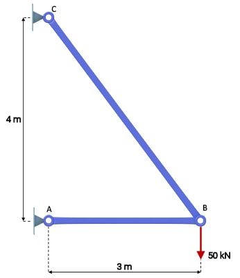
The  force practical at node B, must be transmitted through the structure dorsum into the pin supports at A and C respectively. We can retrieve of the external loads travelling along a load path. The engineer's job is to evaluate the load path and make sure the structural elements along that path tin withstand the stresses induced past the loads being transmitted.
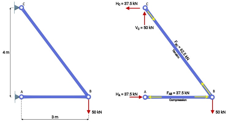
Using the three equations of statics ( ,
,  and
and  ), the reactions at A and C are hands evaluated;
(1) 
Confirm these values yourself through calculation. In order for these reactions to develop at the supports, member AB must transmit a compression force of  while member BC transmits a tension forcefulness of
  . Nosotros tin can run across this indicated on the right manus load path diagram below. By the finish of this tutorial, yous will exist comfy determining these load paths for statically determinate truss structures.
2.0 Joint Resolution Method of Truss Analysis
Now that nosotros've clarified what a truss is and the concept of a load path describing the transmission of forces through the structure, the adjacent task is to work out how to place the forces along the load path. In other words nosotros want to be able to work out the forces adult in each of the members in response to external loading.
We'll focus on 2 similar techniques that make utilize of the equations of static equilibrium. They are:
- the joint resolution method
- the method of sections
In both cases, we must first decide the support reactions for the structure. Only then tin nosotros employ the joint resolution method, method of sections or a combination of both.
Nosotros'll showtime past considering the joint resolution method which involves evaluating force equilibrium at each joint or node and using the equations of statics to solve for the unknown member forces. Consider the two bar truss again, shown below every bit a free body diagram.
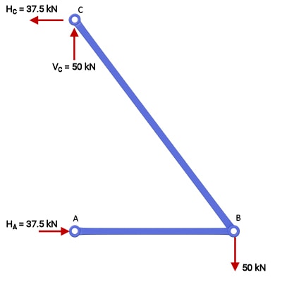
The articulation resolution method requires us to evaluate the sum of the forces meeting at a articulation. These forces can exist resolved into two orthogonal (mutually perpendicular) directions allowing united states of america to evaluate 2 equations of forcefulness equilibrium. Thus we accept ii equations from which we can determine two unknowns. So, using the method of joints we can but offset at a joint that has a maximum of two unknown fellow member forces. For this uncomplicated structure, nosotros can consider any of the three nodes, we'll start with node B.
Nosotros isolate the articulation by cut the members meeting at that articulation. Making these cuts we reveal the internal member forces, for now labelled every bit  and
and  where the
  indicates we are assuming (until proven otherwise) that the forces are tension forces.
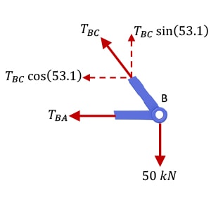
A free body diagram of the joint is and then evaluated by taking the sum of the forces in the horizontal and vertical management and equating them to cypher to reveal the unknown member forces (recollect two unknowns, then ii equations required). In the post-obit assay, note that basic geometry gives u.s. the bending  . Now consider force equilibrium of articulation B:
(2) 
Notice here that evaluates to a positive number and therefore our assumption that the force in fellow member BC is a tension force is right. At present evaluating horizontal forcefulness equilibrium,
(3) 
Here the negative value tells united states that the force in member BA is actually opposite to our initial supposition and therefore a compression strength. This completes the assay of this elementary truss. It is worth reflecting on the direction of the arrows indicating tension and compression beneath.
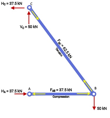
For member AB in compression, the yellow strength arrows betoken outward, as if to resist a force compressing the member. By the same analogy, the force arrows for member BC point inwards every bit if to resist a force trying to pull apart or stretch the bar. This can initially be counter-intuitive so make sure y'all're happy with this convention before proceeding, otherwise you'll get terribly confused afterwards.
That's the joint resolution method in a nutshell. Nosotros've only demonstrated it and then far for a very simple truss but the process is exactly the aforementioned no matter how big your truss gets. As long as you tin identify a node within your truss structure that has no more than 2 unknown member forces passing through the node, you can deploy the joint resolution method. We'll come across this in activity again a piddling later!
iii.0 Method of Sections Truss Analysis
Now we tin can consider the other tool at our disposal, the method of sections. Instead of isolating a single joint, the method of sections involves us making an imaginary cut through the entire structure. In doing so, we reveal the internal fellow member forces in the members our plane cuts through. We tin then evaluate equilibrium of either of the 2 sub-structures created by the cut.
This method of structural analysis brings into play a third equilibrium equation; because all of the forces interim on the sub-structure no longer all pass through the same point, we tin can now consider the sum of the moments virtually any point which, is our tertiary equation.
Since the structure is in a state of static equilibrium, the sum of the moments (only like the forces) must equal zero. Then we now have iii equations of statics at our disposal. The key affair to remember with the method of sections is that our airplane cannot cutting through more than three members with unknown fellow member forces.
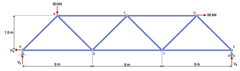
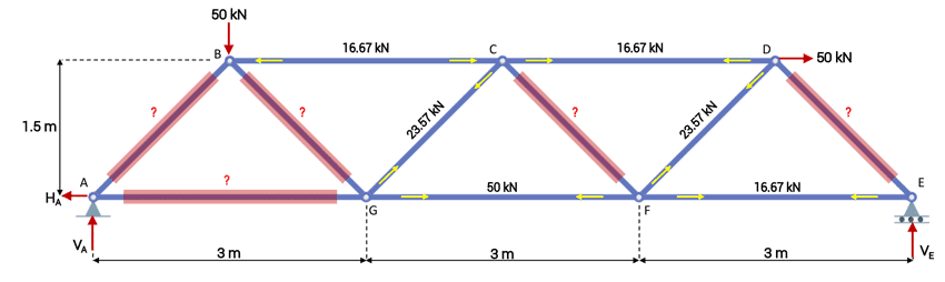
As usual, the best way to understand this technique is by working through an example. So consider the simple Warren truss below subject area to bespeak loads at nodes B and D.
Reactions
Equally with any statically determinate analysis, the get-go task is to determine the support reactions. We'll showtime by considering the sum of the moments almost point A which must equal zip. We'll presume clockwise moments are positive.
(four) 
(5) 
(6) 
Next we tin can evaluate the sum of the forces in the vertical or  direction to determine the remaining unknown vertical reaction. Bold upwards pointing forces are positive, we have,
(seven) 
(eight) 
(nine) 
Finally, by inspection we tin say that the horizontal reaction is,
(10) 
Department one
To demonstrate the method of sections, let's kickoff by considering a vertical department cutting the structure between nodes G and C. This will cut through members BC, CG and GF which will reveal the internal forces in those members. Equally nosotros do for the method of joints, we'll assume these forces are tension forces and therefore the force arrows betoken away or out of the cut member.
The sub-construction to the left of the cut (pictured below) must now be in a state of static equilibrium under the influence of the externally applied forces, reactions at A and internal member forces, ,  and
and  . Then, we have 3 unknowns and three equations, we're now able to solve for the member forces.
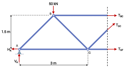
We'll get-go by using the moment equation and evaluating the sum of the moments about point G. Point G is a good starting betoken considering 2 of our unknowns pass through it and and so will disappear from the moment equation, leaving only that we can direct solve for.
(eleven) 
(12) 
(xiii) 
Now the fact that evaluated to a negative number means that the strength arrow actually points in the opposite direction, meaning that is a compression strength,
(14) 
Next, if we evaluate the sum of the forces in the vertical direction nosotros can solve for ,
(15)
(xvi) 
(17) 
And finally we tin can determine the remaining unknown by considering horizontal force equilibrium and assuming forces to the right are positive,
(xviii) 
(19) 
(20) 
(21) 
The method of sections is a helpful technique, because we can make a cutting anywhere within the construction to make up one's mind the fellow member forces. We don't need to know any of the other internal member forces. And then for example, nosotros didn't need to know what the forces were in members AB, AG or BG before we made our cut.
If we were only using the joint resolution method, nosotros would have to work our way from the back up nodes towards the surface area of interest and evaluate the forces at each node forth the way, which could become slow for a larger structure.
Allow'southward try another cut, this time with a cutting plane betwixt D and F and because the sub-structure to the correct of the cut plane.
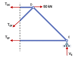
Again annotation that our cutting plane has cutting through no more that three members with unknown internal member forces. This is key, if our cutting reveals any more than that three unknowns, nosotros won't have enough equations to solve for them all. A sensible starting point this time is to consider the sum of the moments almost point D, eliminating ii unknowns from the moment equation.
(22) 
(23) 
(24) 
Evaluating vertical force equilibrium side by side,
(25)
(26) 
(27) 
And finally, horizontal force equilibrium,
(28)
(29) 
(thirty) 
(31) 
Now is a practiced time to summarise where we are in the analysis,
We could continue to employ the method of sections and make more cuts in the structure or we could utilise the method of joints to end out our analysis. For the sake of variety, we'll use the method of joints from here on.
Joint A
Starting with joint A nosotros cutting the members meeting at the joint to reveal their unknown internal forces,
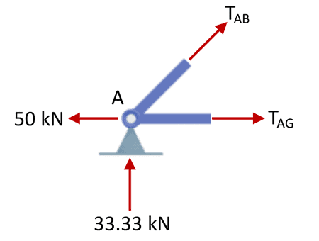
Recall from our word above, we merely have 2 equations to work with now and so nosotros can just evaluate joints with a maximum of 2 unknown member forces. Evaluating vertical force equilibrium first,
(32)
(33) 
(34) 
(35) 
Now considering horizontal strength equilibrium,
(36)
(37) 
(38) 
(39) 
Joint B
Moving on to joint B,
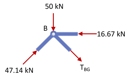
We only demand to evaluate vertical force equilibrium to determine our simply unknown here,  .
.
(twoscore)
(41) 
(42) 
(43) 
Articulation C
Because horizontal force equilibrium of joint C next.
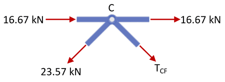
(44)
(45) 
(46) 
(47) 
Joint E
And finally, vertical force equilibrium of joint E.
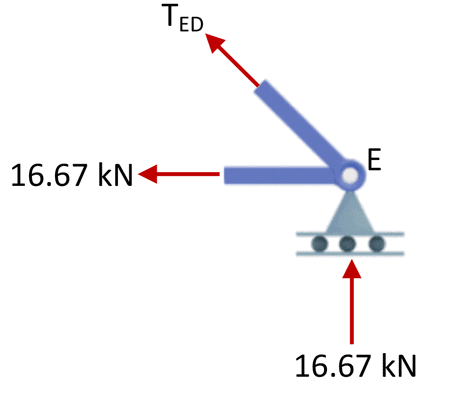
(48)
(49) 
(50) 
(51) 
Now that we've evaluated all of the internal member forces, we tin can summarise them below.
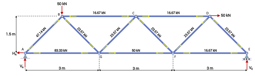
Hopefully these few examples have given you lot a clear idea of exactly how to become about analysing a statically determinate truss. The loftier level steps are the same each time; first identify your support reactions, so commencement working your way through the structure using the articulation resolution method, method of sections or both.
Remember, when using the joint resolution method you have two equations to work with so analyse joints that take up to ii members with unknown forces coming into the articulation. When using the method of sections, you unlock a third equation to work with, the moment equation. And then now, whatever section you take through the structure, information technology cannot cut through more than that three members with unknown internal forces.
When trying to perform a truss analysis, you lot may notice that y'all can't first the analysis or part-mode through you can't advance any further. There may be no suitable cuts to make or joints to analyse. In this case you're likely dealing with a statically indeterminate truss and the methods discussed here won't work.
I've written a little more on the concept of truss indeterminacy in this mail and I've written up a full tutorial on an alternative solution method that is applicable to indeterminate trusses in this mail. So check those out for more information.
That'southward it for truss analysis in this mail, see yous in the adjacent 1.

Source: https://www.degreetutors.com/truss-analysis-using-method-of-joints-and-sections/
Posted by: riverahiscriand68.blogspot.com
0 Response to "How To Read Truss Shop Drawings"
Post a Comment